
The VertDesk v3 Plus is the perfect desk for the power user who needs a ton of lifting capacity for their workspace. This desk features two motors and the lifting capacity of 450 lbs., all while maintaining a lift speed of 1.24” per second!
This desk provides a tremendous amount of power on top of a ridiculous amount of customizability, having 93,632 different combinations available. With that being said, when you receive your VertDesk v3 Plus, there will be some assembly required. In this blog, we’ll teach you how to properly assemble your new desk so you can put it to use.
Full Disclaimer: We are an office furniture dealer and sell some of the products we review. To learn more about the products we sell, our review process and why you can trust us, please visit: Why we’re different. Who is BTOD.com and The Breakroom Blog?
How To Assemble VertDesk v3 Plus
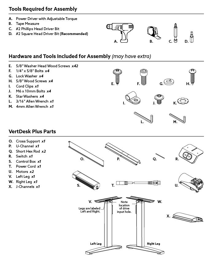
There are a few different tools you need to efficiently assemble your VertDesk v3 Plus. To start, you’ll need a power driver with adjustable torque (cordless drill). This is something that we highly recommend because it’s much easier to drive the screws into the wooden work surface. We also recommend using a #2 square head driver bit instead of a #2 Phillips Head Driver Bit, because it is easier to use the square bit when drilling the screws into the work surface. Other items on the list include a tape measurer and hardwood/tools that are included with your VertDesk.
Before you begin step one of assembly, you’ll want to take note of a few things. First, your new work surface should be laid out on top of a sturdy surface and protected by a moving blanket. Next, your new surface should be laid out upside down so that the pilot holes are facing towards you. For this step, you’ll need the right and left legs, two motors, and two of the short hex rods.
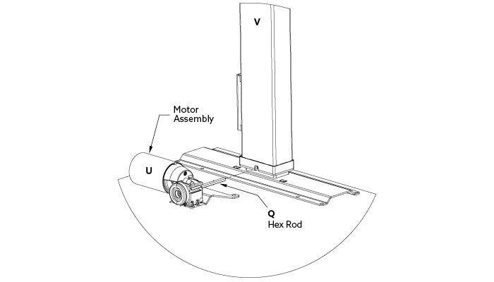
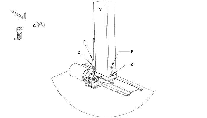
Once you’ve organized everything you can begin attaching the legs. You’ll notice that the legs have a sticker telling you if they’re meant for the right or left side. It is very important you put each leg on its proper side. To begin, place the left leg column onto the work surface and align with the pre-drilled pilot holes. It’s important to ensure the leg is in its lowest position. Next, insert the short hex rod through the motor assembly, starting at the bracket side of the motor. Place that same hex rod into the left leg drive input hole. If the hex rod isn’t properly aligned with the drive input, slightly rotate the motor 1/6 or 1/3 of a turn, then fully slide rod into the drive input hole. Repeat this same process using the right leg column and short hex rod. After the hex rod is installed, tighten the motor mounting bolts on both legs.
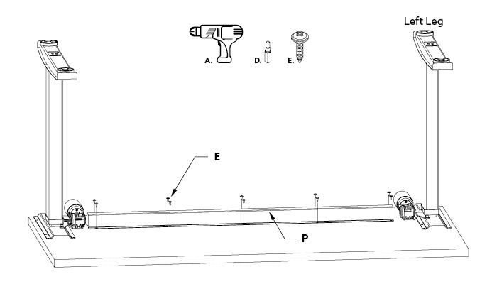
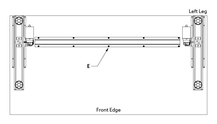
The next step will be installing the u-channel support, which will add stability to your work surface. This installation will depend on your work surface, as the hole placement will vary depending on the width of the table. If you are using a BTOD work surface, simply line the pre-drilled holes with the input holes on the u-channel support and install the screws. You’ll notice that the u-channel is directional and has holes that are closer on one end then the other. The side that has the holes closest to the end of the u-channel should be closest to the left leg assembly For proper alignment of pre-drilled holes, start the screws, but do not fully tighten until all are installed.
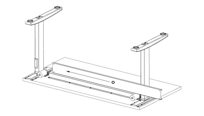
The next step in your VertDesk Plus assembly is attaching the cross-support to both leg assemblies. The recommended way to install this is to slide the cross-support ove`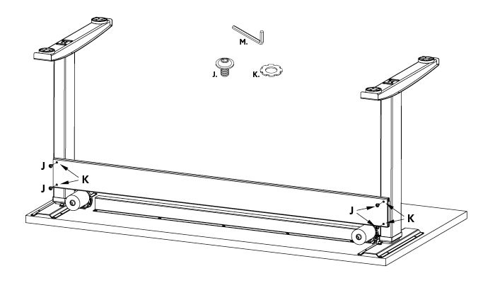
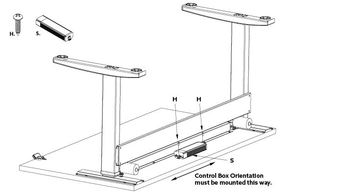
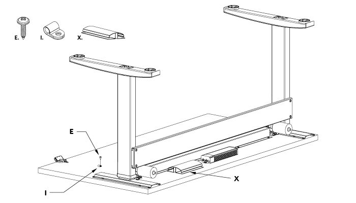
Next, install your control box. This can be installed in any location between the legs of the desk, but it’s important to note that it remains parallel with the desk because of the gyrosense technology and how it understands collision avoidance. To attach to the desk, simply screw to the work surface with the 5/8” wood screws.
Once you’ve attached the control box, you are ready to place the wire management system. Before attaching, make sure you like the placement of the wire management system because a 3M adhesive is used, which is very difficult to remove and cannot be reattached once it’s pulled off.
When you’re ready to attach, pull off the backside of the adhesive tape and place the system where you’d like on the desk. Press down firmly to ensure it’s connected nicely to the work surface.
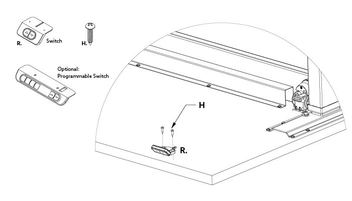
Now that the wire management is attached, you can attach the up and down switch to the desk as well. First align the switch with the holes on the (when upright) front left side of the desk. Please note that the predrilled holes are only a suggestion, and you may make your own holes to attach your up and down switch. To attach to the desk, simply screw to the work surface with the 5/8” wood screws.
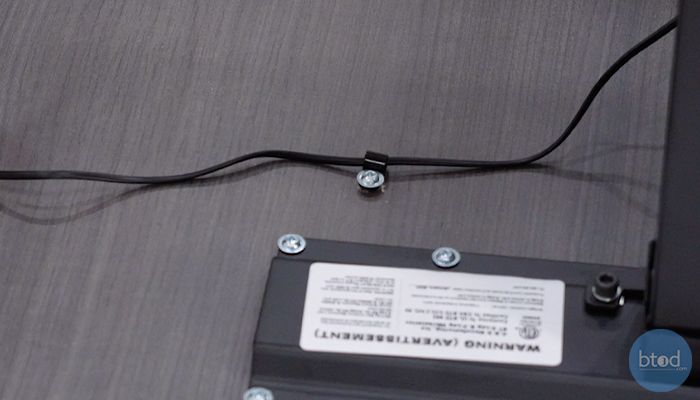
Next, you’re ready to attach the cord clip with another 5/8” wood screw. First, take the cord clip and slide it onto wire attached to the switch. There aren’t any predrilled holes for this, so install the cord clip wherever you feel most comfortable.
Finally, you’re ready to start inserting the cords to make the desk operational. The first cord you’ll start with will be the left motor and left leg assembly. You’ll notice the cords have ties on them, so to stay organized you can pull out enough of the wire to plug into the control box, leaving the rest of cord still tied. You’ll also see there are two different inputs on the control box; it doesn’t matter which you choose.
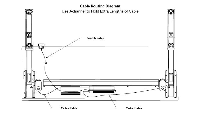
Do the same with the right-side motor on the right leg assembly. Because this is a further reach, you’ll likely need to untie to reach the control box. Once that is clicked into place on the control box, you’re ready to install the power cord. This will also be attached to the control box and can be run through the wire management system.
Now that all you have everything installed, you’re ready to flip your desk over and test to make sure everything is running properly. We recommend getting someone to help you flip the desk, as it is very heavy. To do the startup procedure, press and hold the down button and you’ll see that the desk will calibrate by moving up and downward. Once that is complete, it has been calibrated and it is ready for normal operation.